
Disassembly of G2 and G3 controls
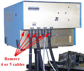
| Disconnect the 120V cord to the control.
Remove the 4 or 5 cables going to the back of the control Place the control on a work bench. Remove the blue cover |
 |
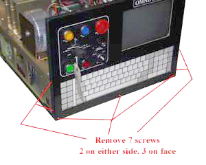
| Take the front face plate assembly off.
To do this remove 7 phillip screws.
|
 |
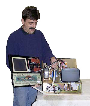
| Lay the face plate assembly on the side. | 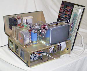 |
| Disconnect the keyboard and cable harness that attach the front assembly to the control.
Put the front assembly to the side. |
 |
| Disconnect the cables at the front of the control. If you have a C axis machine, there will be two more cables. Another connect card cable and Spindle encoder cable. Be careful. These cables can be mixed up. Mark them if they are not already color coded. If they go back together incorrectly, you will not have correct spindle control. | 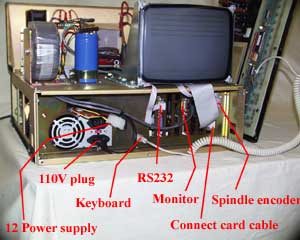 |
| Remove the 7 phillips screws holding the top half of the control down to the lower half. | 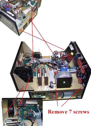 |
| Carefully lift the lower half off the upper half and put it aside. | 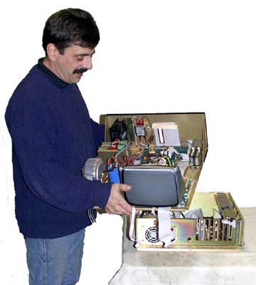 |
| The lower half is now accessible for service. | 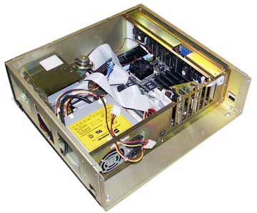 |
|
|
 |
|||||||||||||||||